DTV and Hummer info
Hacking a "C64 on a chip"
How the ADCRD routine works
The ADC used on the Hummer pcb is a clone of the SNAD01C. This 8-channel device is hidden under the tiny epoxy blob between the ASIC (big blob) and the power regulator. The device itself is smaller than 2mm square.
What's it for? An Analog-Digital Converter is used to sample voltages, and return those values to the main processor. It can be used to read a potentiometer, read temperature (via thermistors), light sensors, position sensors, etc.
Despite it's 8-channel capablities, only one channel of the ADC is available.
The code follows the protocol outlined in this image:

- Bring up START signal, then drop it
- Start CLOCK cycle, each subsequent bit transfer takes one full cycle (HI & LO.) The original routine included delay loops to normalize the clock, but they weren't needed.
- Send 'ADC command'-- 100
- Send channel # -- 000
- The DIO line is bit 0 of userport-- since each bit can be shifted (to the right) into the bit 0 position, these 6 bits are stored backwards: '000001'. Of course, only one bit is actually set, but the routine was written so other cmds could be sent to the ADC, if needed.
- Two empty clock cycles follow, while the ADC is capturing the voltage level and converting to digital. Or are these two extra bytes simply padding, for controllers or UARTS which can only transfer data in a complete byte?
- 8 bits of data are now sent from the ADC
- A 9th bit is supposedly sent, but isn't documented in this drawing (the routine adds another clock cycle after the data, but doesn't save the "PDS" bit (power-down status?) This extra clock tick is included, but probably not needed--the next START signal would likely reset the ADC. NOTE: This extra clock cycle has been removed from the newer (V0.5+) routines.
The INIT routine
The ADC has several other operational commands, some of which are used to initialize the device:
- A 'Control Register Setting' function (011), which sets pullup or pulldown resistors (digital input only, NA), where the ADC gets it's reference voltage (internal or REF pin.) This is sent in a 4-bit chunk (0001)
- A 'Channel Attribute Setting' function (001), which sets the input channels to analog or digital. 8 bits of data are sent to the ADC, (1) = analog, (0) = digital. We want all analog--(11111111).
- A 'Channel Wakeup Function Setting' (010), also followed by 8 bits, (1) = enable, (0) = disable. Enable all--(11111111)
- The last two settings would probably function the same if only channel #0 were enabled. We have info from 'macbthpsw' (Thanks, Robin) that the Hummer init code set ALL the channels to analog and wake-enabled, so I followed that. Since only Channel #0, is connected, the other channels shouldn't matter.
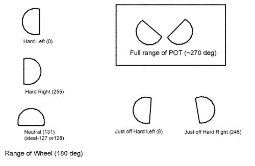
POT range-of-motion, w/approx. ADC values

The range of motion conforms perfectly with the actual resistance range of the POT, which also fits perfectly with the travel of the steering wheel.
Tests with a VOM confirm that the full +3.3V - GND is sampled by the ADC. The angles noted above were not taken with
the steering wheel installed, but are eye-balled and approx.
Drawing view is looking at the top of the POT (the bottom of the Hummer board.)